|
vDash Specifications |
Virtual Dashboard Utility for PC |
Click on Image Hotspots (above) to learn more
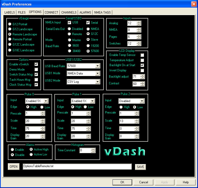
All vGauge Remote sensor units and Display Head options can be set from preference dialog and saved to selected file for later loading onto attached unit. The number of virtual display pages and screen size is set from this dialog.
The vGauge
section is used to select which type of unit is being programmed. The vDash
screen size will change to match the proportions of the selected display so
they can be configured with the correct number and types gauges. Some displays
can support both portrait and landscape view modes.
G12 displays are monochrome 320 X 240 pixels
G12C are color 320 X 240 pixels
G18 displays are color 480 X 272 pixels.
The vGauge Remote
buttons are set for 320 X 240 pixels
 Options Section
 Used to enable
status messages from vGauge-Remote units
Enable vSwitch - When checked, will enable vSwitch buttons
in the vDash Toolbar on the main screen. A vSwitch module must be installed in
the vGauge-Remote senor unit for the buttons to perform any switching
functions.
Demo Mode - When checked, will enable demo mode on the
vGauge-Remote unit. In demo mode, sample data stored in the vGauge-Remote unit
will be played back on all outputs instead of live data from the sensors. This
can be useful to verify operation of all data links to displays and computer
without needing to attach any sensors. For normal operation with live data from
sensors, this button should be unchecked (disabled).
Switch Status -When checked, will enable status messages
from vGauge-Remote containing the states (ON/OFF) of each switch. This message
is used to update the vSwitch buttons on the main vDash toolbar to show the
current switch state. A vSwitch module must be installed in the vGauge-Remote
sensor unit for these messages to be valid. If no vSwitch module is installed,
this button should be unchecked (disabled) to improve performance.
Tach Hours - When checked, will enable tachometer hours
messages to be transmitted from vGauge-Remote. When any of the 3 pulse inputs
go above 1 per second, an accumulative clock is incremented to keep total
run-time for each pulse input accurate to 1 second. This information is stored
in non-volatile memory and can be displayed in the vDash title bar if this
option is enabled (checked). If display of tachometer hours is not required,
disable (uncheck) this option to improve system performance.
Clock Status - When checked, will enable real-time date
and hours messages to be transmitted from vGauge-Remote. An on-board clock
keeps track of current date and time. This information is stored in non-volatile
memory and can be displayed in the vDash title bar if this option is enabled
(checked). The initial clock settings are performed in the NMEA TAGS tab of the preferences dialog. If display of Date and Time
is not required, disable (uncheck) this option to improve system performance.
 SERIAL/USB Section
This section is
used to configure the
NMEA INPUT - Used to select which input is used to
listen for incoming NMEA 0183 data on the vGauge-Remote or Display Head. vGauge
Display heads have both a serial and USB port and can listen for NMEA data on
both ports. vGauge-Remote units also have a serial and USB input and can listen
for NMEA data on both. For normal operation on all units, both options should
be enabled (checked). If both options are disabled (unchecked) it my be impossible
to FLASH program the unit as at least one input port should be enabled. This
setting does not apply to vGauge Display heads and should be set NMEA for compatibility
Serial Data Out - This option is used to select the format
for data output on the serial port on vGauge-Remote units.
Disabled
- Inhibits any output on the Serial port
NMEA - Outputs NMEA 0183 $IIXDR type sentences for all selected sensors and is
used for Display Heads and vDash. This
is the normal (default) setting when using the serial port for attachment to PC
and vDash.
Remote - Outputs a custom $IIXDR NMEA sentence only for currently active gauges
on a selected display page. This format embeds gauge layout information in each
sentence so that the display head does not need to pre-store this information.
This special format allows a vGauge Display heads to be remotely controlled
from a vGauge-Remote unit without requiring download of labels and page layout
information. In this manner, a Display Head receives all the gauge layout information
for the current screen from the Remote unit and can send request to show a new
page layout. This special format can improve performance by decreasing the
amount of data being transmitted and allows changes to gauge layout on the Remote
unit to be instantly seen on any attached Display Head. It is not recommended to use this mode when attaching the serial port to
vDash as not all sensor data is transmitted and vDash will not be able to
configure any new layout screens due to the missing data.
G12C - Outputs a custom message used only by G12C and G18C color display heads.
Only outputs current gauge layout information from vGauge-Remote. Display Heads
can send request to new page layouts. There is no need nor is there any option
to program G12C or G18C display heads as all configuration is set at the
factory. These color display heads get all operating data from Remote unit
using this data format. This option must be set if using a G12C or G18C on the
serial port of a vGauge-Remote unit and can not be used by any other type of
display or vDash. Do not use this mode
when attaching the serial port to vDash as it will not be able to decode or
display the data.
Mode - This option is only used by G12 display
heads. When set to Slave, G12 display heads get all gauge label information
from vGauge-Remote units. If set to Master, gauge label information stored in
each individual display head will be used. This can be useful if connecting
multiple display heads to vGauge-Remote and wanting to have different gauge
display labels show up on individual units. For normal operation choose SLAVE mode for all units.
Baud Rate - This important setting configures the
communication speed (BAUD) for the selected serial port and must be set to
match the target device. For most applications the default rate of 57600 should
be used. When connecting the serial port to a PC or another vGauge Display
head, this speed must be set to match on both ends or no data will appear. The
same holds true if using a USB to Serial adapter to attach to a PC. The vDash program
Baud Rate must be set to match the serial port rate. The vDash Baud rate is set
in the CONNECT tab of the
Preferences Dialog.
 USB1/USB2 Section
This section is
used to configure the USB ports on vGauge-Remote or vGauge Display heads.
vGauge-Remote contains two directional USB ports while vGauge Display heads contain
a single USB port.
USB ports can be
MASTER or SLAVE. Most computer USB ports are MASTER while devices that attach
to them are SLAVES (printers, memory sticks) vGauge Display head USB ports are
SLAVE and can attach directly to any PC USB port for programming. vGauge-Remote
USB ports are configured as MASTER to allow Display Heads to directly attach to
them. This presents a problem in that a vGauge-Remote USB port can not be
directly connected to a PC USB port without a special adapter that allows two
MASTER USB ports to communicate. Chetco Digital Instruments has developed
several types of USB adapters that will allow connection to HOST PC USB,
ETHERNET, BLUETOOTH, or WI-FI types of interfaces. Consult you vGauge-Remote
manual or contact Checto Digital Instruments to obtain information on these
products.
USB1 Mode - This setting is used to configure the data
format and mode for the primary USB port on vGauge-Remote units.
Disabled - Disables all transmission out of the USB port. Does not effect input of
data on USB. Can be used to improve performance if the primary USB port is not
being used.
NMEA Mode - Enables NMEA 0182 $IIXDR data transmission
required by vDash and older G12 display heads. This mode must be selected if
using vDash to monitor data or configure units on this port.
G12C Display - Enables the use of G12C type of displays on
this port. When this format is enabled, vDash can not be used on this port. It is
important not to enable both the serial port and USB ports in G12C mode at the
same time as this will prevent vDash from being able to display any data. vDash
can still be used to reprogram (FLASH) an attached unit in this mode.
NMEA Remote - Enables a custom NMEA $IIXDR data format
that embeds gauge layout information in each sensor sentence for display on G12
display heads. This allows G12 display heads to SLAVE to vGauge-Remote units so
no programming is required to update gauge layout information on attached
display heads. This mode can not be used with G12C and G18C display heads.
NMEA Status - A special mode that allows standard NMEA
0183 $IIXDR sentences to be transmitted while data logging to memory stick on
USB port 2. Select this mode if you need to use vDash or some other attached
device on USB port 1 while logging data on USB port 2. Normally output is
disabled on USB1 when data logging on USB2. Data input is not possible on USB1
when this mode is enabled.
USB2 Mode -These settings apply to the second USB port
(USB2) which is normally used for data logging to an attached USB memory stick.
NEMA LOG - Enables logging to memory stick in NMEA 0183 format. Logging is not
active on unit power up and must be started and stopped via commands from a G12C
display head or attached PC. The log file can be directly read by vDash for
playback.
NMEA LOG PUP - Same as NMEA LOG but is automatically
enabled when remote unit is powered up with memory stick in USB port 2. Log
data is appended to end of current log file.
CSV LOG - Enables logging to memory stick in comma separated file format (CSV)
commonly used by spreadsheet programs. Gauge Labels are output on first line
when logging starts followed by matching sensor data on each new line separated
be commas. Logging is not active on unit power up and must be started and
stopped via commands from a G12C display head or attached PC. The log file can
not be directly read by vDash for playback.
CSV LOG PUP - Same as NMEA LOG but is automatically
enabled when remote unit is powered up with memory stick in USB port 2. Log
data is appended to end of current log file.
NMEA Status mode - This mode allows two G12 style display
heads to be attached on both USB1 and USB2 ports. This mode can not be used for
G12C or G18C displays. vDash can be used to display gauges when using appropriate
USB adapter but can not perform programming operations on this port.
 INPUTS Section
Used to configure the number and types on data inputs for vGauge-Remote and vGauge Display heads
ANALOG – vGauge-Remote units can accept up to 12 analog inputs while some vGauge display heads can accept up to 4 analog inputs. Most display heads can not accept any analog inputs. Set to 12 for default.
NMEA – All vGauge units accept some NMEA 0183 types of inputs such as $IIXDR and GPS sentences on separate channels. This setting is used to assign selected NMEA inputs to unused channels on vGauge-Remote units. Normally, vGauge-Remote units have 12 analog inputs and 2 Pulse inputs thus leaving 2 spare channels for NMEA inputs. It is possible to decrease the analog input channels to 8 and increase the NMEA inputs to 6 by adjusting these parameters. THIS OPTION HAS NO EFFECT ON vGAUGE DISPLAY HEADS.
PAGES – Gauge configurations are contained in a set of up to 8 customized pages which can be sequenced using front panel buttons or touch screens. This parameter controls the number of pages before cycling back to the first page. This setting should be the same for both vGauge-Remote units and attached vGauge Display Heads.
Switches – This parameter controls the number of vSwitch pushbuttons displayed on the main screen. A vSwitch module must be installed in the vGauge-Remote unit for any remote switching functions to become active. Any changes will not take effect until the next time the vDash program is started.
 PULSE Section
Each vGauge unit has one to three pulse inputs normally used for RPM or MPH functions. The calculated display value is based on the number of pulses received within a 0.5 second interval multiplied by the PULSE SCALE factor. The Pulse TIME Constant is used to control averaging pulses; larger value performs more averaging and can slow down update rates. If not using a Pulse Input, set the INPUT to disabled. Pulse inputs enabled with 2X to 8X multiplier increase the collection time interval from 0.5 seconds up 4 seconds thus increasing the resolution for slower pulse inputs.
Pulse 2 is a special case for vGauge display heads as it provides the base timing for display updates
INPUT – Used to enable Pulse input and determines the amount of time used to calculate pulse rates.
Disabled – Turns off pulse calculations and can improve performance if not needed.
Enabled 1X – performs pulse rate calculations and base update rate of 1 second.
Enabled 2X – performs pulse rate calculations and base update rate of 2 seconds. Improves slower pulse rate accuracy with increased latency.
Enabled 4X – performs pulse rate calculations and base update rate of 4 seconds. Improves slower pulse rate accuracy with increased latency.
TimeBase2 – Resets unit time base from default of 1 second to 0.5 (1/2) second. Allows faster display updates and data logging if using fewer inputs. CAN CAUSE UNIT INSTABILITY IF TOO MANY INPUTS ARE ENABLED. USE WITH CAUTION.
TimeBase3 – Resets unit time base from default of 1 second to 0.33 (1/3) second. Allows faster display updates and data logging if using fewer inputs. CAN CAUSE UNIT INSTABILITY IF TOO MANY INPUTS ARE ENABLED. USE WITH CAUTION.
TimeBase4 – Resets unit time base from default of 1 second to 0.25 (1/4) second. Allows faster display updates and data logging if using fewer inputs. CAN CAUSE UNIT INSTABILITY IF TOO MANY INPUTS ARE ENABLED. USE WITH CAUTION.
PRESCALE - is used to divide incoming pulses before measurement. This is very useful on inductive pickups witch count gear teeth on flywheels and can be 100 – 200 times the actual value. Use this setting to divide incoming pulses from 1 to 256.
SCALE - is used to multiply the measured pulse rate by a constant values to generate the correct display value.
For example – an 8 cylinder engine generates 4 sparks (pulses per revolution). One revolution per minute (1 RPM) = 4/60 pulses per second. Therefore, to display the calibrated RPM for an 8 cylinder engine = Pulse Rate X (60/4) = Scale of 15.
A six cylinder engine generates fewer pulses per second (3) and therefore requires a larger SCALE value (20) to give the correct RPM
TIME - is used average pulse calculations to decrease noise. Larger TIME values perform more averaging but also increase latency. Normal values are 50-75.
DISPLAY GAIN scales the graphic indicators to a
desired range without changing the actual digital readout. Tachometers can have
display range from 3000 to over 10000 while speedometers may only go up to 100.
To accommodate this wide range of display options, use the DISPLAY setting to
scale the dial range. A higher value will max the display indicator sooner then
a smaller value. Start with a setting of 1 and increase if the dial indicator
does not travel full range.
 ALARMS Section
Alarm functions can be globally enabled or disabled by setting the ALARMS radio buttons. If driving a pizo alarm directly then choose ACTIVE HIGH. Other wise if driving a high current alarm through a relay choose ACTIVE LOW.
ENABLE – Global enable of all alarms
DISABLE – Global disable of all alarms
ACTIVE HIGH – Any alarm condition will generate a high level output on vGauge-Remote Alarm output
ACTIVE LOW – Any alarm condition will generate a low level output on vGauge-Remote Alarm output
 Display Section
Some vGauge models have options to configure LCD screen settings. The Display section allows control over temperature compensation and backlight state.
ENABLE TEMP SENSOR Some LCD Displays have a built-in temperature sensor for performing automatic contrast adjustment.
TEMPERATURE ADJUST will automatically alter LCD screen contrast on select models based on a user customizable calibration table. If disabled, LCD screen contrast can be performed using standard calibration.
BACKLIGHT ON START is used on selected models to enable LCD backlight on power up if desired.
INVERT DISPLAY Select LCD displays can show reverse screens (Black background) useful for night viewing.
BACKLIGHT Adjust sets the brightness of the backlight on some monochrome LCD screens. Lower values are dimmer while higher values are brighter. Range is 0 to 100.
CONTRAST allows the contrast on monochrome LCD screens to be increased or decreased for best viewing. Increasing this vale will lighten the screen while decrease will darken the screen. Range is 0 to 100
All option parameters are saved to to a user specified file for later loading to SeaGauge or vGauge unit. Any changes to the OPTIONS dialog must be SAVED before exiting the dialog or they will be lost. Use the OPEN button to select a new Options file. Use the SAVE button to change file location or rename a file.
info demo specs prices products order support contact
(c) Copyright 2008 Chetco Digital